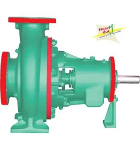
Pulp Stock Pump | Reliable Pumping Solution for Paper & Pulp Industry
In the paper and pulp industry, the pulper machine is one of the most critical pieces of equipment. Engineers, students, and maintenance teams often search for a pulper machine diagram to clearly understand how the machine works, how its components are arranged, and how pulp is prepared efficiently. A diagram helps visualize the process and simplifies learning, troubleshooting, and maintenance.
This article explains what a pulper machine is, the importance of a pulper machine diagram, its main parts, and how the system works in real industrial conditions.
What Is a Pulper Machine?
A pulper machine is used in the paper and pulp industry to break down raw materials such as waste paper, cardboard, or virgin pulp into a uniform slurry. This slurry, known as pulp, is then processed further to manufacture paper products.
Pulper machines are widely used in:
Paper mills
Recycling plants
Packaging industries
Tissue and board manufacturing units
Why Is a Pulper Machine Diagram Important?
A pulper machine diagram provides a clear visual representation of how the machine is built and how each component functions together. It is especially useful for:
Understanding the working principle
Identifying individual parts
Learning material flow inside the pulper
Maintenance and troubleshooting
Training new operators and technicians
Without a diagram, it can be difficult to understand how raw material enters the machine and transforms into usable pulp.
Main Parts Shown in a Pulper Machine Diagram
A typical pulper machine diagram includes the following key components:
1. Pulper Tank (Vat)
This is the main chamber where raw material and water are mixed. The tank is usually cylindrical or oval and designed to withstand continuous operation.
2. Rotor or Impeller
The rotor is mounted at the bottom of the pulper tank. It creates strong agitation, helping break down paper fibers and mix them with water.
3. Drive Motor
The motor provides power to rotate the rotor. It is designed for high torque and continuous duty.
4. Screen Plate
Located near the bottom of the pulper, the screen plate controls pulp consistency by allowing properly processed fibers to pass through while rejecting oversized materials.
5. Inlet Opening
Raw material such as waste paper or pulp sheets is fed into the pulper through this opening.
6. Discharge Outlet
The prepared pulp exits the pulper through the discharge outlet and moves to the next processing stage.
7. Water Inlet
Water is added through dedicated inlets to achieve the required pulp consistency.
Each of these parts is clearly labeled in a pulper machine diagram, making it easier to understand their roles.
Pulper Machine Working Principle (Explained Using the Diagram)
The pulper machine diagram helps explain the working process step by step:
Raw material is fed into the pulper tank
Water is added to soften the fibers
The motor drives the rotor at controlled speed
The rotor creates turbulence, separating fibers
The slurry passes through the screen plate
Prepared pulp exits through the outlet
This continuous process ensures uniform fiber separation and efficient pulp preparation.
Types of Pulper Machines
Based on the diagram and construction, pulper machines are classified into:
Low consistency pulpers – Used for gentle fiber separation
High consistency pulpers – Used for energy-efficient pulping
Drum pulpers – Used in large recycling plants
Vertical pulpers – Common in compact paper mills
Each type has a slightly different diagram, but the core components remain similar.
Industrial Applications of Pulper Machines
Pulper machines are used in:
Paper recycling plants
Newsprint manufacturing
Carton and board production
Tissue paper production
Packaging industries
The pulper machine diagram helps engineers select the right pulper type for each application.
Maintenance Benefits of Understanding the Diagram
Knowing the pulper machine diagram helps maintenance teams:
Identify wear parts quickly
Understand rotor and screen alignment
Prevent blockages and overloads
Reduce downtime
Improve machine life
A clear diagram reduces guesswork during servicing.
Conclusion
A pulper machine diagram is more than just a drawing—it is a powerful learning and operational tool. It helps engineers, operators, and technicians understand machine structure, working principles, and component functions clearly.
By studying the diagram, industries can improve operational efficiency, reduce maintenance issues, and ensure smooth pulp production. Whether for training, troubleshooting, or system design, understanding the pulper machine diagram is essential in the paper and pulp industry.